EN
EN
 FR
FR
 JA
JA
 RU
RU
 ES
ES

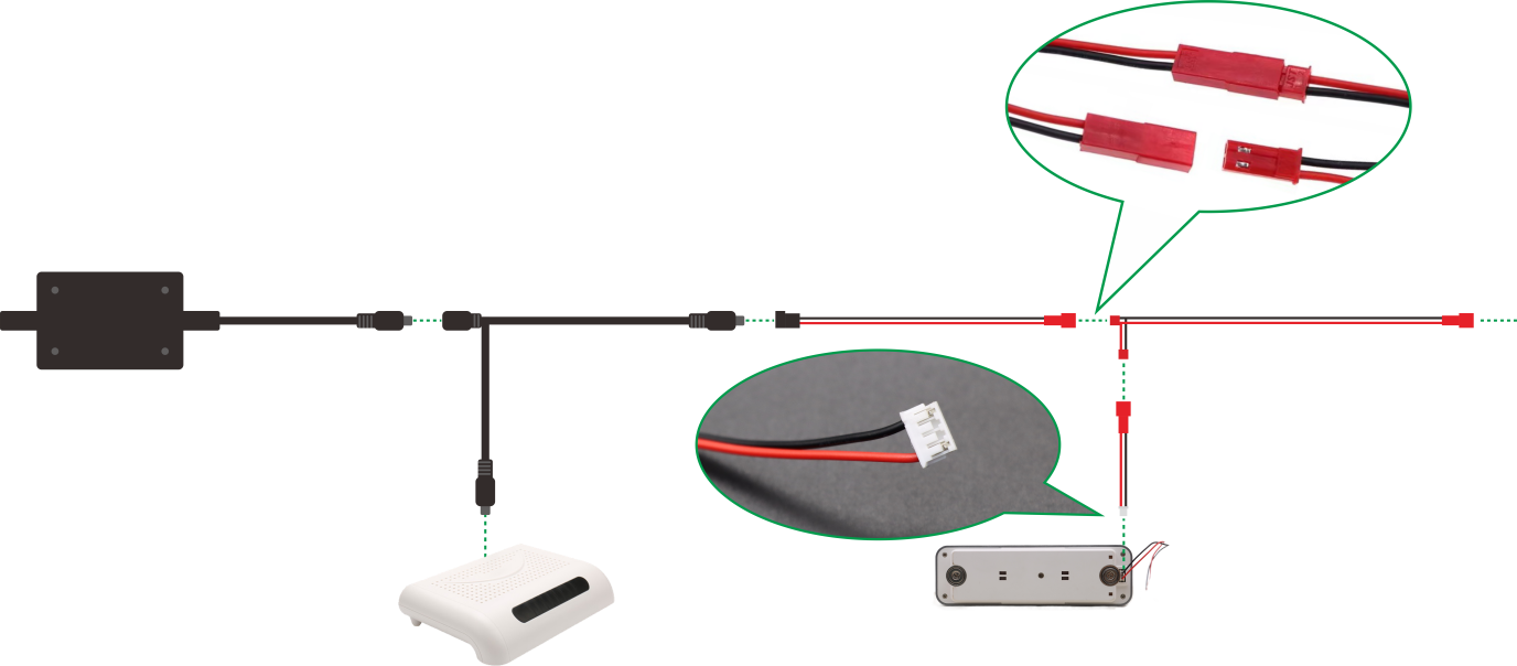
Step-by-Step Guide to Connecting the PLC
When setting up your device, it’s important to follow the correct connection sequence to ensure stable performance and safety. The diagram above shows the complete wiring process. Below is a detailed explanation of each step:
1. Start with the Main Power Source
On the left side, connect the main power supply to the system. Ensure that the power cable is securely inserted into the input port. This provides the necessary power for all connected devices.
2. Connect the Control Module
Next, link the control module (the small white box shown in the picture) to the main line. The connector is designed to fit in one direction only, so align it carefully and push it in until you hear or feel a click.
3. Extend the Power Line
The main cable continues forward with extension connectors. These connectors allow you to increase the length of the wiring as needed without affecting signal transmission or power delivery.
4. Attach the Split Connection
At the highlighted section, you will see a red plug-in connector. This is a split connection that branches the power line to additional devices. Match the male and female connectors according to the guiding slots and lock them together. This ensures a firm and safe connection.
5. Connect Additional Devices
From the split connection, connect the secondary device (shown in the lower-right zoom-in). The wires are color-coded—red for positive (+) and black for negative (–). Double-check the polarity before plugging in to avoid any damage.
6. Final Check
-
Confirm that all connectors are firmly locked.
-
Ensure there are no exposed wires.
-
Verify that the polarity matches (red to red, black to black).
-
Power on the system and check if all devices respond correctly.